Driving a Ceiling Fan from Home Assistant with a CC1101 and ESP32-S3
🇫🇷 Bonjour
TL;DR: My ceiling fan remote is a dumb 433 MHz ASK/OOK transmitter, so I gave its signal a brain. Using an ESP32-S3, a CC1101 sub-GHz transceiver and ESPHome, I built a little gateway that captures the remote’s frames and replays them — the fan and its light are now first-class Home Assistant entities, drivable from buttons, automations and voice assistants, with no vendor cloud involved. This post walks through the hardware, the YAML configuration, and the gotchas (half-duplex radio, SPI pin assignment), with Hermes acting as my AI guide along the way.
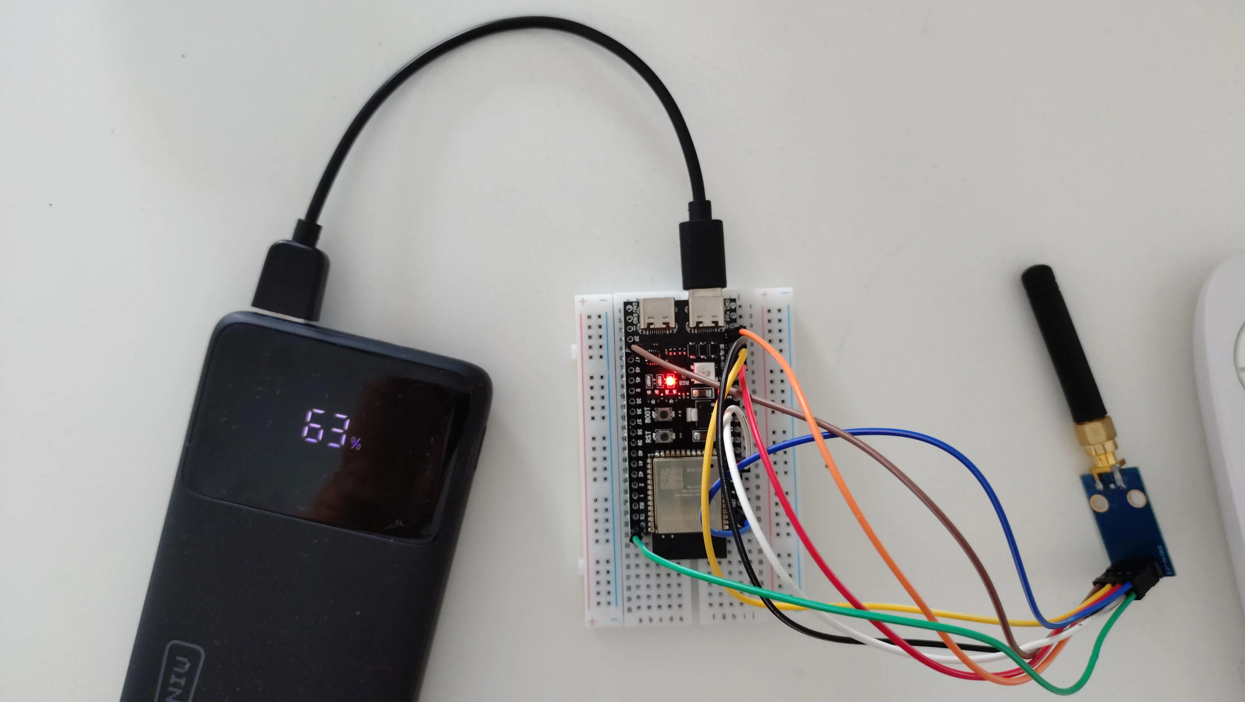
Context
Recently, I discovered Home Assistant and started falling down the rabbit hole of home automation. A few connected light bulbs later, I wanted to go further. My main pain point was finding the remote of my ceiling fan: most of the time I had to search everywhere just to switch on the light in the room. Surely Home Assistant could handle that!
Most ceiling fans are controlled through a handheld RF (Radio-Frequency) remote on 433.92 MHz, ASK/OOK modulation. This means the remote sends a signal, and the receiver catches the sequence and executes an action.
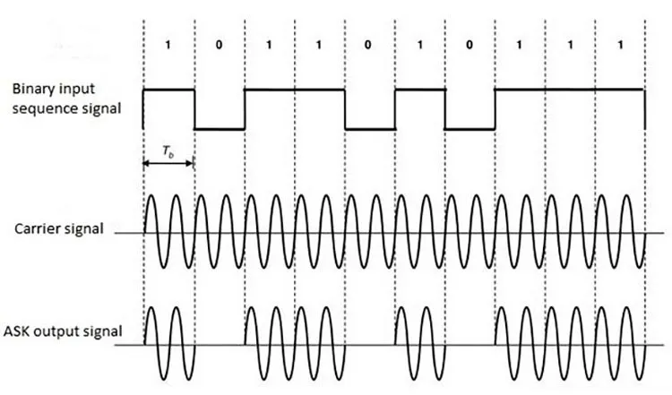
So we just have to capture the signal, and replay it. Which means we need a receiver/emitter.
There are some products that do exactly this:
- BroadLink RM4 / Tuya RF bridges — work, but are closed black boxes that depend on a vendor cloud.
- Sonoff RF Bridge — flashable with ESPHome, but limited to a single protocol and only 433 MHz ASK/OOK.
- A dedicated 433 MHz transceiver on an ESP32 — the route taken here, using a CC1101 sub-GHz radio module. It is cheap, well documented, and fully supported by ESPHome through the
cc1101component.
So I chose the last option. It was my entrypoint to the ESPHome world.
One thing worth knowing upfront: RF hardware and embedded development were brand-new territories for me. I went through this whole project with Hermes — an AI agent from Nous Research — acting as my guide: understanding ASK/OOK modulation, choosing the radio module, writing and debugging the ESPHome configuration. Honestly, I couldn’t have done it without AI acting as a support for this project.
ESPHome
ESPHome is a firmware framework that lets you describe an ESP32 board in a single YAML file: which pins are connected to which sensors, which entities should be exposed, and so on. It compiles that description into a firmware image, and the device connects to Home Assistant automatically — no cloud, no vendor app. Changing the configuration is just a YAML edit followed by an over-the-air update.
The CC1101 is interesting because it is a real transceiver (TX and RX) tunable from 300 to 928 MHz, with configurable modulation and output power. Unlike a cheap 433 MHz super-regenerative transmitter, it can both capture the remote’s frames and replay them.
Hardware
The CC1101 module
An 8-pin breakout board (Amazon link) exposing:
| Pin | Name | Direction | Role |
|---|---|---|---|
| 1 | GND | - | Ground |
| 2 | VCC | in | Power, 1.8–3.6 V (use 3.3 V) |
| 3 | GDO0 | out | General-purpose digital output (TX) |
| 4 | CSN | in | SPI chip select |
| 5 | SCK | in | SPI clock |
| 6 | MOSI | in | SPI data in |
| 7 | MISO/GDO1 | out | SPI data out |
| 8 | GDO2 | out | Second digital output (used for RX) |
The ESP32-S3 board
An ESP32-S3-N16R8 (16 MB flash, 8 MB PSRAM). The ESP32-S3 has a
flexible GPIO matrix, but a few pins have special roles worth knowing
about:
- GPIO0 is the BOOT/strapping pin.
- GPIO19/GPIO20 are USB D-/D+.
- GPIO11/GPIO12/GPIO13/GPIO10 are the hardware FSPI pins
(
FSPID/FSPICLK/FSPIQ/FSPICS0) — ideal for driving the CC1101 over IOMUX at full SPI speed.
Wiring
| CC1101 Pin | ESP32-S3 GPIO | Function |
|---|---|---|
| 1 (GND) | GND | Ground |
| 2 (VCC) | 3V3 | Power |
| 3 (GDO0) | GPIO7 | TX data out |
| 4 (CSN) | GPIO10 | SPI CS0 |
| 5 (SCK) | GPIO12 | SPI clock |
| 6 (MOSI) | GPIO11 | SPI MOSI |
| 7 (MISO) | GPIO13 | SPI MISO |
| 8 (GDO2) | GPIO21 | RX data out |
The ESPHome configuration
ESPHome ships a
cc1101 component that wraps
the radio, plus the classic remote_transmitter / remote_receiver
components that implement the actual 433 MHz protocol stack on top of
it. Let’s build the configuration step by step.
Step 1: board and radio
First the boilerplate: the board, Wi-Fi, and the cc1101 hub itself
(talking over SPI). The on_boot trigger puts the radio in RX mode
right away so we can start capturing immediately:
# Board: Generic ESP32-S3 Board (Generic)
esphome:
  name: esp32-s3-n16r8
  friendly_name: ESP32-S3-N16R8
  on_boot:
    then:
      - cc1101.begin_rx

esp32:
  variant: esp32s3
  framework:
    type: esp-idf

logger:

api:
  encryption:
    key: ...

ota:
  - platform: esphome
    password: !secret esp32_s3_n16r8__ota_password

wifi:
  ssid: !secret wifi_ssid
  password: !secret wifi_password

captive_portal:

spi:
  interface: hardware # IOMUX, full SPI speed
  clk_pin: GPIO12 # SCK  → CC1101 Pin 5  (FSPICLK)
  mosi_pin: GPIO11 # MOSI → CC1101 Pin 6  (FSPID)
  miso_pin: GPIO13 # MISO → CC1101 Pin 7  (FSPIQ)

cc1101:
  cs_pin: GPIO10 # CSN → CC1101 Pin 4 (FSPICS0)
  frequency: 433.92MHz
  output_power: 10
  modulation_type: ASK/OOK
  symbol_rate: 5000
  filter_bandwidth: 200kHz
Step 2: the receiver
Now the remote_receiver component. It listens on GDO2 and dumps every
captured frame as a list of pulse durations. The default dumpers try
to “decode” raw pulses against every known protocol — see the trap
below — so we restrict dump: to raw.
The on_raw trigger does two jobs: it logs the pulses in small chunks
(so each line fits in the ESPHome log buffer and can be copy-pasted
from the logs), and it stores the last burst in a global when learning
mode is on:
# Global to store the learned signal
globals:
  - id: learned_code
    type: std::vector<int32_t>
    restore_value: no
  - id: learning_mode
    type: bool
    initial_value: "false"
  - id: signal_learned
    type: bool
    initial_value: "false"

# RF receiver (via GDO2)
remote_receiver:
  id: rf_receiver
  pin: GPIO21
  tolerance: 50%
  filter: 200us
  dump:
    - raw
  idle: 10ms
  on_raw:
    then:
      - lambda: |-
          // Log in chunks so each line fits the ESPHome log buffer (~256 chars).
          // Reassemble: part0 + ", " + part1 + ", " + ... -> code: [...]
          ESP_LOGI("raw_code", "Pulses: %d", x.size());
          const int chunk = 40;
          for (int i = 0; i < (int)x.size(); i += chunk) {
            std::string s;
            for (int j = i; j < (int)x.size() && j < i + chunk; j++) {
              if (j > i) s += ", ";
              s += std::to_string(x[j]);
            }
            ESP_LOGI("raw_code", "part %d: %s", i / chunk, s.c_str());
          }

          // Learning mode: store this burst and stop listening
          if (id(learning_mode)) {
            id(learned_code).clear();
            for (int32_t val : x) {
              id(learned_code).push_back(val);
            }
            id(signal_learned) = true;
            id(learning_mode) = false;

            std::string preview = "";
            int count = 0;
            for (int32_t val : id(learned_code)) {
              if (count > 0) preview += ", ";
              preview += std::to_string(val);
              count++;
              if (count >= 20) {
                preview += "... (" + std::to_string(id(learned_code).size()) + " total)";
                break;
              }
            }

            id(last_signal).publish_state(preview.c_str());
            id(learn_status).publish_state("Signal learned! " + std::to_string(id(learned_code).size()) + " pulses.");
          }
Trap for new players: the IR dumpers (
pronto,nec,beo4…) will happily try to “decode” 433 MHz RF frames and produce garbage like Pronto frequency006D(= 38 kHz IR). Restrictingdump:to RF protocols avoids pages of false positives in the logs.
Step 3: the transmitter
The transmitter is connected to GDO0. The subtlety is that the CC1101
is a half-duplex radio: it can be in RX mode or TX mode, never
both. The on_transmit / on_complete automations of
remote_transmitter handle the switching: enter TX mode just before
sending, and go back to RX mode right after:
# RF transmitter (via GDO0)
remote_transmitter:
  id: rf_transmitter
  pin: GPIO7
  carrier_duty_percent: 100%
  on_transmit:
    then:
      - cc1101.begin_tx
  on_complete:
    then:
      - cc1101.begin_rx
Step 4: Home Assistant-facing entities
Finally, we expose small helpers so the whole learning workflow can be driven from Home Assistant (or the ESPHome web UI): a switch to arm learning mode, a button to replay the learned signal, and text sensors to see what was captured:
switch:
  - platform: template
    name: "Learning Mode"
    id: learning_mode_switch
    icon: "mdi:school"
    lambda: "return id(learning_mode);"
    turn_on_action:
      - lambda: |-
          id(learning_mode) = true;
          id(learn_status).publish_state("Waiting for signal... Press remote now!");
      - logger.log: "Learning mode ON - press your remote"
    turn_off_action:
      - lambda: |-
          id(learning_mode) = false;
          id(learn_status).publish_state("Learning cancelled");
      - logger.log: "Learning mode OFF"

button:
  - platform: restart
    name: "Restart"

  - platform: template
    name: "Replay Learned Signal"
    icon: "mdi:replay"
    on_press:
      - lambda: |-
          if (!id(signal_learned) || id(learned_code).empty()) {
            ESP_LOGW("replay", "No signal learned yet!");
            id(learn_status).publish_state("No signal to replay - learn one first!");
            return;
          }
          ESP_LOGI("replay", "Replaying %d pulses...", id(learned_code).size());
          id(learn_status).publish_state("Transmitting...");
      - remote_transmitter.transmit_raw:
          carrier_frequency: 0Hz
          code: !lambda "return id(learned_code);"
      - lambda: |-
          id(learn_status).publish_state("Signal transmitted!");
          ESP_LOGI("replay", "Replay complete");

  - platform: template
    name: "Clear Learned Signal"
    icon: "mdi:delete"
    on_press:
      - lambda: |-
          id(learned_code).clear();
          id(signal_learned) = false;
          id(last_signal).publish_state("(empty)");
          id(learn_status).publish_state("Signal cleared");
          ESP_LOGI("learn", "Learned signal cleared");

text_sensor:
  - platform: template
    name: "Last Received Signal"
    id: last_signal
    icon: "mdi:signal"

  - platform: template
    name: "Learn Status"
    id: learn_status
    icon: "mdi:information"

binary_sensor:
  - platform: template
    name: "Signal Learned"
    icon: "mdi:check-circle"
    lambda: "return id(signal_learned);"
Capturing the fan remote
With the radio listening, pressing a button on the fan remote produces
a raw dump in the ESPHome logs that looks like this (truncated):
[remote_receiver:...]: Received raw: [-1076, 320, -744, 718, -340, 337, ...]Each value is a pulse duration in microseconds; positive = mark (carrier on), negative = space (carrier off). The remote sends the same burst about 5 times per keypress, with a ~10 ms gap between bursts.
The capture workflow:
- Toggle Learning Mode (or press the button on the device page).
- Press a button on the physical remote — the first burst is stored, the rest are ignored.
- Check the Last Received Signal sensor and Replay Learned Signal to verify the fan reacts.
Once a frame is validated, I bake it into a dedicated button so it
survives reboots and no longer depends on the volatile global. A
single captured burst (here 90 pulses) is replayed directly with
remote_transmitter.transmit_raw:
button:
  - platform: template
    name: "Fan Replay"
    icon: "mdi:fan"
    on_press:
      - remote_transmitter.transmit_raw:
          code: [
              -1076,
              320,
              -744,
              718,
              -340,
              337,
              -718,
              341,
              -720,
              733,
              -318,
              342,
              # ... about 90 pulse values in total ...
            ]
          repeat:
            times: 5
            wait_time: 10ms
Press that button from Home Assistant → the fan reacts exactly as if the physical remote had been pressed. Goal #1 done.
Result
Since the CC1101 listens to everything on 433.92 MHz, nothing prevents it from handling more than one device. I first wired it up for the ceiling fan, then realized the exact same setup could absorb the second fan in the other room:
- Fan #1 and Fan #2 are now both controllable from Home Assistant via dedicated template buttons that replay each captured frame (speeds 1–6, off, light).
The ESP32-S3 + CC1101 combo acts as a single, centralized 433 MHz gateway: one device, one antenna, two fans, fully scriptable from automations and voice assistants.
Home Assistant
Once the device is flashed and connected to Wi-Fi, it announces itself
to Home Assistant through the native ESPHome API — no manual
integration needed. Every button, switch, text_sensor and
binary_sensor from the YAML appears as an entity automatically.
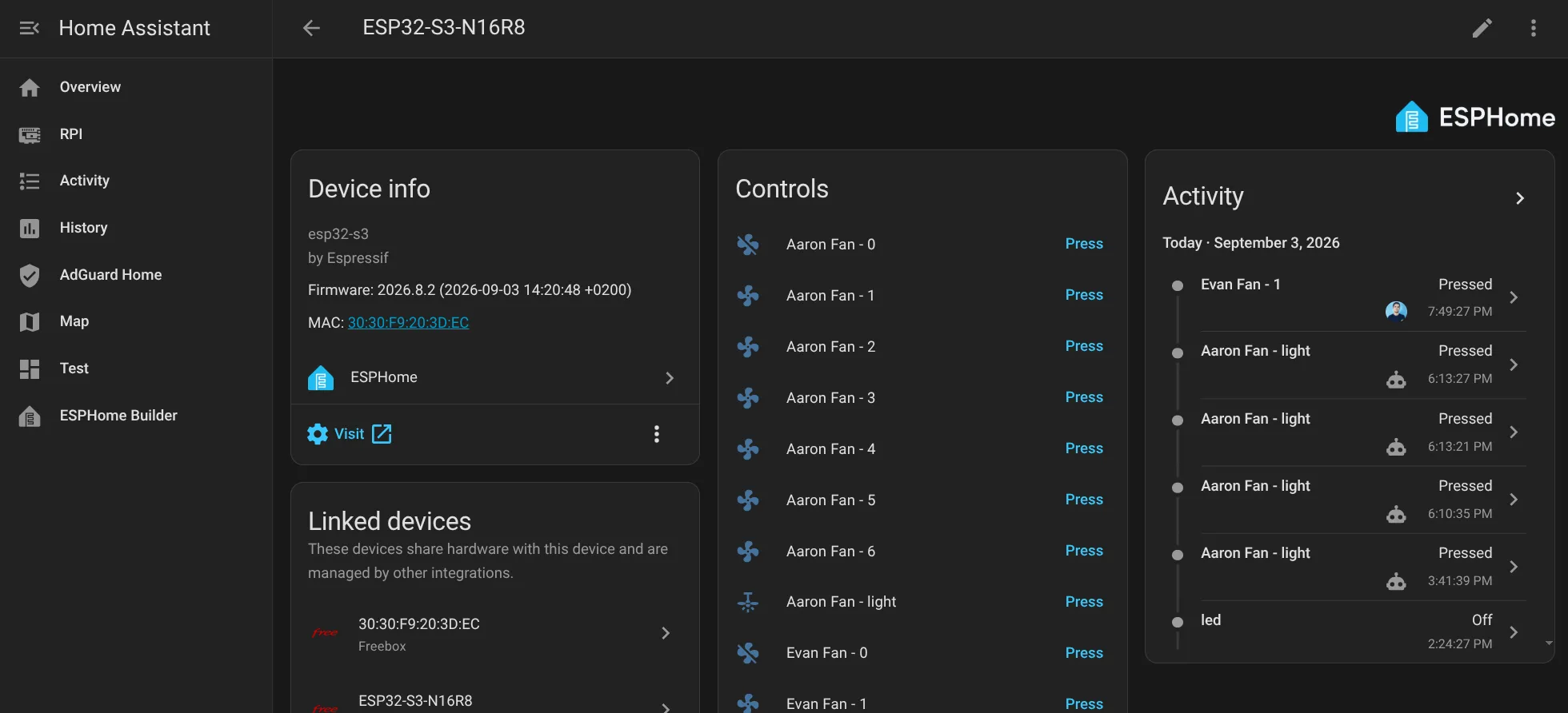
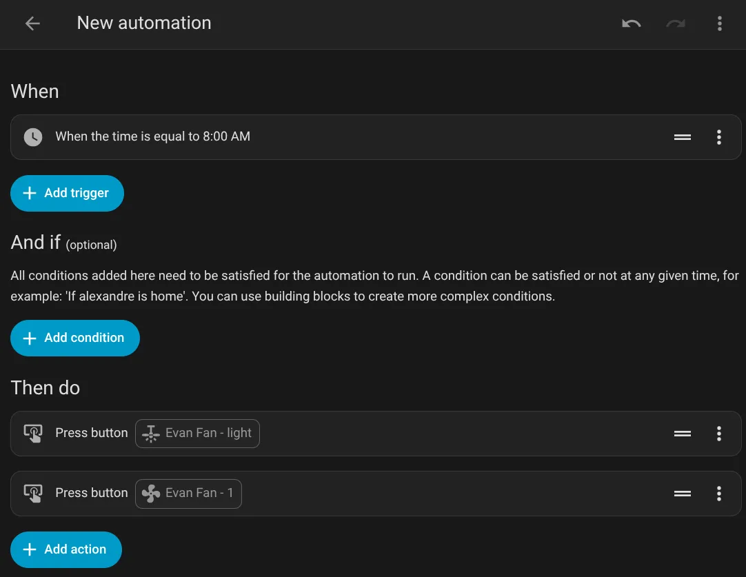
And since the buttons are plain entities, they can be driven by scenes, schedules, or voice assistants out of the box.
Takeaways
- The CC1101 + ESPHome stack is a genuinely good way to integrate “dumb” 433 MHz devices. It is open, flashable, and lets you both capture and transmit with the same hardware.
- Pin assignment matters. Putting SPI CS on the hardware FSPICS0 pin (GPIO10) was the difference between a dead radio and a working one.
- Half-duplex is the gotcha. The radio must be explicitly switched
between RX and TX — once you wire
on_transmit/on_completecorrectly, everything else “just works”. - AI as a pair programmer. I guided this project with Hermes (Nous Research) — it closed the knowledge gap on RF and ESPHome and unblocked me at every step. This kind of project used to require prior embedded experience; now curiosity is enough.
🤖 This post was written with a little help from AI
An LLM helped me write this article: drafting, translating and proofreading. The ideas, the project and the code are mine — so no, it is not 100% AI slop.